Stat Tracker Development - Problems and Solutions
With any project there will undoubtedly be problems that one encounters especially when working with new things. In this log I want to mention some problems I encountered and their solutions.
Problem: Intermittent Issues with timing on the main loop code.
For this problem I would expect the reader to have some understanding of how coding works on a microcontroller but I will attempt to explain it in laymen terms.
Other clues: Invalid timer values.
In my code, I use a timer peripheral on my microcontroller (mcu) to handle all the timing on the stat tracker. This involves having a interrupt routine every time the timer overflows. During this routine I use a 32 bit variable that gets incremented. Every certain amount of overflow represents 1 millisecond. millis_cnt is the variable which tracks the number of milliseconds since the stat tracker has been on. Anyone who works with Arduino should be familiar with millis(), this is basically the same thing. The code below is the interrupt service routine (ISR).
void  timer0_ISR() __interrupt (INT_NO_TMR0)
{
    static  volatile  uint8_t overflows = 0;
    // Interrupt flag auto cleared.
    overflows++;
    if(overflows >= OVERFLOWS)
    {
        overflows = 0;
        millis_cnt++; // increment millis
    }
}
On 8 bit microcontrollers, one needs to understand that when using 32 bit numbers, the microcontroller has to work on the number in 8 bit pieces (bytes) which would involve multiple instructions. The ISR can happen at anytime after each instruction which means that while millis_cnt (the 32 bit timer variable) is being accessed, the ISR can increment it. This can lead to an invalid millis_cnt value that was read. For example: Lets say that we tried to read the millis_cnt number when it was 0x0000FFFF or 1111 1111 1111 1111 in binary. We read the first 2 bytes as 0xFFFF before the interrupt happens and increments the millis_cnt. The new millis_cnt is 0x00010000. As we finish the routine we return back to reading the remaining 2 bytes of millis_cnt but the value has changed. Now we get 0x0001FFFF which is not correct. This led to issues where main loop code would get run continuously instead of every 10ms or so that I coded.
Solution: Disable interrupts whenever working on a variable that can change during an interrupt service routine then re enable them after.
EA = 0; // disable global interrupts
prev_millis = millis(); // set before going into loop
EA = 1; // enable global interrupts
I did learn this during school but it's been a long time since I worked on 8 bit microcontroller directly.
Problem: LEDs sometimes flickered.
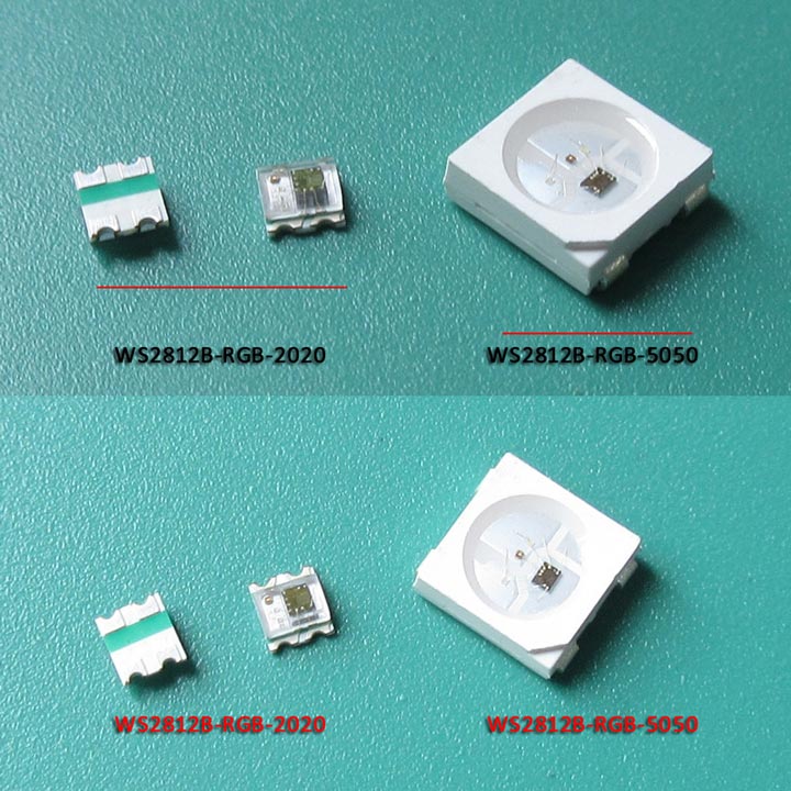
The WS2812 leds require a very specific timing on the bit banging to work properly. I use a smaller 2020 version of the addressable led which has a slightly different timing so for the most part it worked but due to the leds not being perfect from batch to batch, some of leds flickered intermittently.
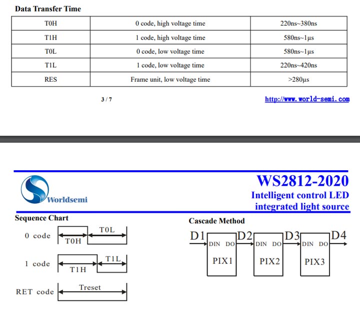
To be exact, the timing for a 1 code high voltage time was 560 ns when the expected was 580ns to 1 us. Since it was so close, it mostly worked.
Solution: Updated the bitbang.c with an extra NOP instruction to adjust the timing to within spec
Problem: Getting signals from the top board to the bottom board in a PCB sandwich
On my first prototype (rev 0.9) I used a single header pin which goes through all the boards and gets soldered on the top and bottom. This seemed a logical solution at first but it comes with some issues.
- Exposed soldered on the top and bottom.
- Harder to disassemble the boards as it requires desoldering now
- Requires extra hand soldering afterwards pcb assembly
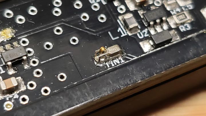
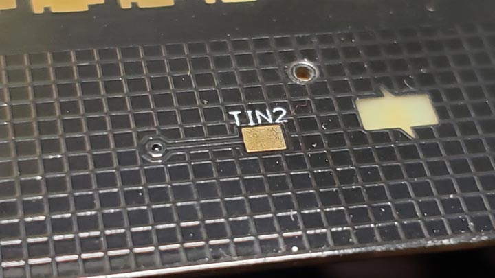
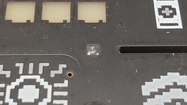
The signals I needed to get from the top board and the bottom board were the touch capacitive signals. Exposed pads are bad because it meant it was susceptible to static discharge. This actually happened and damaged the touch peripheral on the MCU on my prototype. For the next prototype, I used special spring contacts that you would find in a phone. https://lcsc.com/product-detail/New-Arrivals_ECT-818000905_C495010.html With a spring contact on the bottom and a pad to connect to on the bottom of the top board, you now have a really nice solution for getting signals through the board that isn't exposed on the top and is invisible.